tECHNOLOGY Testing
Featured Test Platforms
Grid Integration
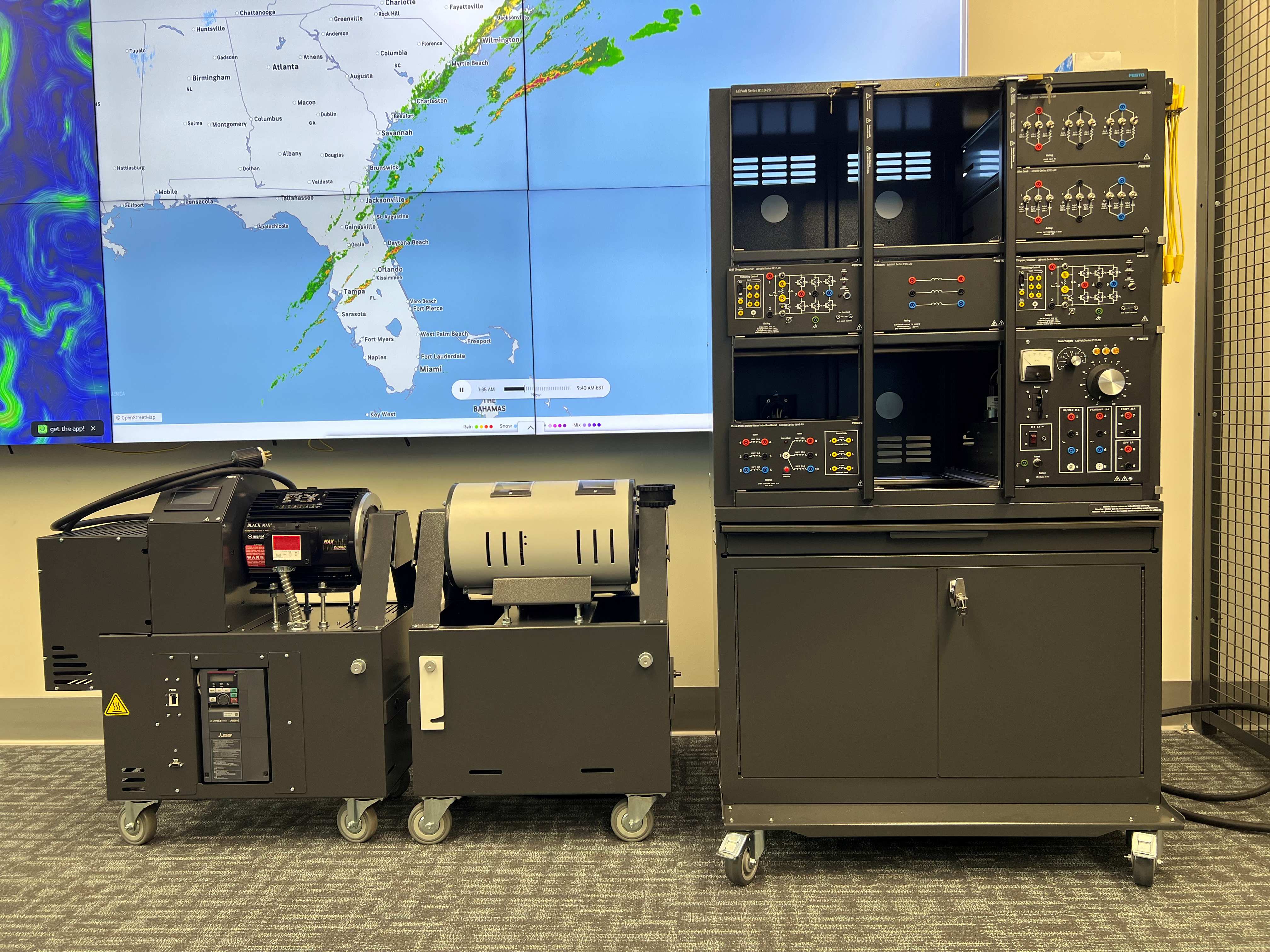
OPAL-RT Hardware-in-the-Loop Energy Systems Simulation System
General System Description
The Center has implemented an OPAL-RT Hardware-in-the-Loop (HIL) Energy Systems Simulation System to support advanced testing and development of marine energy technologies. Hardware-in-the-Loop simulation enables real control hardware, such as controllers, protection relays, and monitoring systems, to interact with a real-time digital simulation of generators, power electronics, and electrical grids.
This approach allows engineers to evaluate system behavior under realistic operating conditions without directly exposing hardware to the risks associated with offshore deployment. Complex scenarios such as grid disturbances, control failures, and varying ocean current conditions can be safely reproduced in a controlled laboratory environment. The HIL platform, therefore, serves as an important bridge between laboratory component testing and full-scale offshore operation.
Detailed System Description
The system is based on an OPAL-RT real-time digital simulation platform capable of executing high-fidelity power system and power electronics models with deterministic real-time performance. The simulator runs models developed in MATLAB/Simulink using the RT-LAB environment and supports high-speed analog and digital input/output interfaces for closed-loop interaction with external hardware devices.
The laboratory platform was originally purchased based on the OPAL-RT Festo 8857 Inverter and Encoder Integration Validation system, which is designed to demonstrate real-time interaction between power electronics drives, motor systems, and real-time simulation models. The system has been further customized and extended by the research team to represent ocean current turbine dynamics and marine energy power conversion systems.
Through this customization, the platform can simulate ocean current turbine behavior, generator dynamics, and grid interaction while interfacing with real controllers, relays, and monitoring devices. When integrated with other laboratory equipment such as the Ocean Current Power Generation Simulator (OCPGS), the OPAL-RT HIL system enables comprehensive testing of control strategies, protection schemes, and condition monitoring technologies for marine renewable energy systems under accurately simulated operating conditions.
Ocean Current Power Generation System (OCPGS)

General System Description
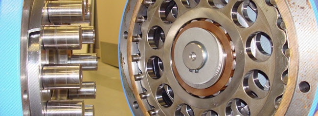
Because testing systems for the first time in the ocean is avoided due to the higher risks and greater unknowns, it is best practice to first “dry” test offshore equipment as much as possible in a laboratory environment. The Center has invested in a laboratory-scale dynamometer, or a device to measure power. Two motors are attached to one another so that one “drives” the other, simulating how the ocean currents might “drive” a rotor attached to a turbine’s shaft. This allows engineers and researchers to set up the offshore power and measurement systems indoors under controlled conditions to explore how to manage the generator when it is put into service offshore.
The dynamometer has been named the Ocean Current Power Generation Simulator, or OCPGS. This capability not only allows SNMREC engineers to configure and prepare technology projects for testing offshore, but is used to optimize intelligent measurement and prognostics systems being developed by researchers. and marine energy technology developers. The OCPGS is also available to commercial developers who wish to pre-configure and test their proposed design generators under controlled, but accurately simulated conditions.
Detailed System Description
The ocean current turbine motor-generator is a 30 HP (22.4 kW) Sumitomo Cyclo 6000 AC Induction Motor (Frame 180 MG, Type TK-F) with rated nameplate values of 230 VAC, 3-Phase, 4-Pole, 60 Hz., 1740 RPM and 74.7 Amps. As a NEMA Design Class A (standard AC induction motor design), the motor features normal starting torque, normal starting current and low slip (the difference between stator and rotor rotational speeds required for motoring and regeneration). Note that nameplate values are cited with respect to 230 VAC operation.
Utility mains at SNMREC are supplied at 208 VAC, so actual ratings are adjusted accordingly to 208 VAC, 54.3 Hz, 27 HP (20kW), and 1606 RPM. Off-shore turbine operation will be supported by a ship-board isolation transformer at 208 VAC as well. The epicycloidal gear (speed-reducer) is also from the Sumitomo Cyclo 6000 family of products (Model CHVM30-6185 YB-25) with rated nameplate values of 30 HP, 25:1 gear ratio, and shaft speed of 70 RPM. The coupled motor and gear are referred to as a Sumitomo Cyclo 6000 Gearmotor. The variable frequency drive is a 30 HP US Drives Phoenix Vector EX AC Drive (Model # E2-0030), and the torque meter is a 7,000 kW S. Himmelstein & Co. MCRT 48007P Non-Contact Horsepower/kW-h meter.
| Location | Ratio to Slow Shaft | Max Speed (rpm) | Max Power (kW) | Speed at Max Power (rpm) |
|---|---|---|---|---|
| Low Speed Shaft |
1:1 |
73 | 20.2 | 73 |
| High Speed Shaft (Prime Mover) | 21.8:1 | 1606 | 20.2 | 1606 |
| High Speed Shaft (Turbine Under Test) | 25:1 | 1575 | 15.5 | 1575 |
Support to access this capability may be available via the U.S. Department of Energy's Testing and Expertise for Marine Energy (TEAMER) program.