Soft Robotic Jellyfish: Design Optimization

Soft Robotic Jellyfish: Design Optimization
Andrew Haselton
The University of Alabama
Dr. Erik D. Engeberg
BioRobotics Lab
This work was supported through the NSF REU Site in Sensing and Smart Systems, funded through NSF Award CNS-2447437.
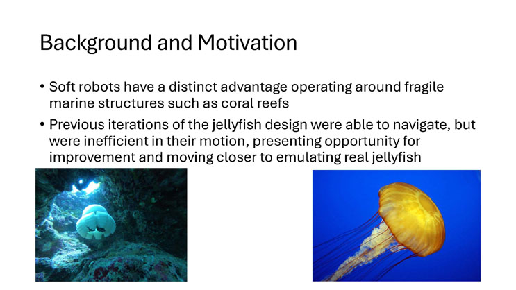
Left image: a soft robotic jellyfish, colored white and gray, hovering near rocks and coral in an underwater cave-like setting with light streaming in from above.
Right image: a real orange sea nettle jellyfish with a domed bell and long trailing tentacles, photographed against a deep blue background.
Bottom right logo: Florida Atlantic University, I-SENSE: The Institute for Smarter Cities, Spaces, and Health, shown with an owl icon.
Background and Motivation
- Soft robots have a distinct advantage operating around fragile marine structures such as coral reefs
- Previous iterations of the jellyfish design were able to navigate, but were inefficient in their motion, presenting opportunity for improvement and moving closer to emulating real jellyfish
Left image: a white soft robotic jellyfish positioned among rocks and coral in a dim underwater cave, with light entering from an opening above.
Right image: an orange sea nettle jellyfish with long tentacles swimming against a bright blue background.
Objectives
- Improve jellyfish design to achieve greater propulsion
- Optimize actuation pattern for propulsion
- Evaluate the impact a bell can have on propulsion
Challenges
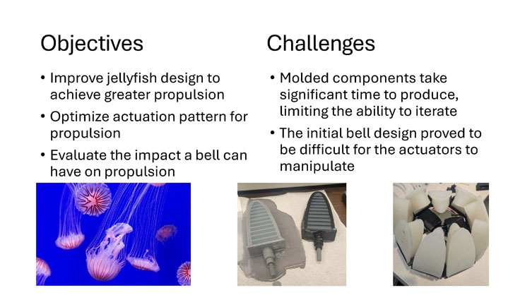
- Molded components take significant time to produce, limiting the ability to iterate
- The initial bell design proved to be difficult for the actuators to manipulate
Left image: several pink and white jellyfish with long trailing tentacles swimming in blue water.
Middle image: two gray ribbed pneumatic actuator components lying on a cloth surface.
Right image: an assembled white robotic jellyfish frame showing multiple wedge-shaped bell segments and internal actuator components.
Design Improvements
- Reoriented actuators
- Improved actuator retention to ensure actuators stay in place during collisions
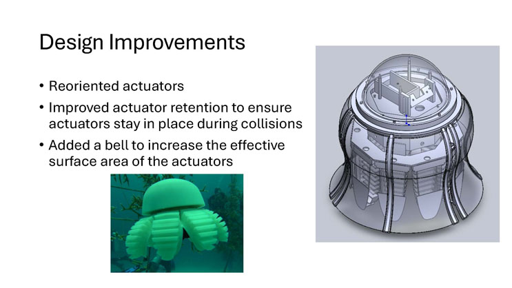
- Added a bell to increase the effective surface area of the actuators
Left image: a green soft robotic jellyfish with a domed top and ribbed actuator legs, resting near underwater plants.
Right image: a CAD rendering of the jellyfish bell assembly, showing a clear domed top, internal support frame, and curved bell panels with attached actuators.
Bell Concepts
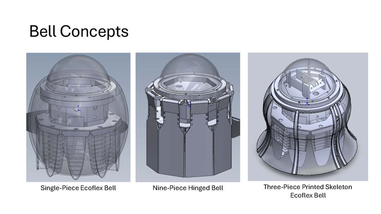
Three CAD renderings of candidate jellyfish bell designs are shown side by side.
Left image, captioned "Single-Piece Ecoflex Bell": a smooth, single continuous domed bell shape with a translucent outer covering over a ribbed internal actuator structure.
Middle image, captioned "Nine-Piece Hinged Bell": a bell made of nine hinged rigid segments arranged around a central frame, giving it a faceted, cylindrical appearance.
Right image, captioned "Three-Piece Printed Skeleton Ecoflex Bell": a bell with a clear domed top and three flexible printed skeleton panels covered in a soft material, flaring outward at the base.
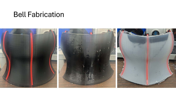
Bell Fabrication
Three close-up photographs show a single flexible bell panel at different stages of fabrication, each with red reinforcement lines running vertically along the panel.
Left image: a black bell panel with red support lines, showing a smooth curved surface.
Middle image: a black bell panel with visible surface texture and residue from the molding or coating process.
Right image: a lighter gray/translucent version of the same bell panel with red support lines, showing a cleaner finished surface.
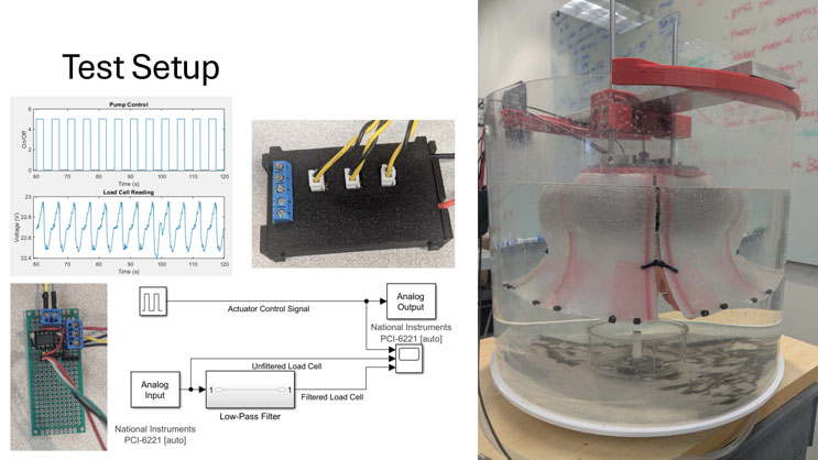
Test Setup
Top left chart, titled "Pump Control": an on/off square wave plotted against time from 60 to 120 seconds, showing the pump repeatedly switching between 0 and 5.
Below it, titled "Load Cell Reading": a voltage plot ranging from about 22.4 to 23 volts over the same time period, showing a repeating oscillating pattern synchronized with the pump control signal.
Top middle image: a black electronics enclosure with three yellow wire connectors and a blue terminal block on top.
Bottom left image: a small green circuit board (PCB) with soldered components and red and black wires attached.
Diagram: a block diagram of the data acquisition and control system. An "Actuator Control Signal" (shown as a square wave) feeds into an "Analog Output" block labeled "National Instruments PCI-6221 [auto]". An "Analog Input" block feeds into a "Low-Pass Filter" labeled "National Instruments PCI-6221 [auto]", which splits into "Unfiltered Load Cell" and "Filtered Load Cell" signals, both feeding into a data logging block alongside the actuator control signal.
Right image: a large cylindrical clear water tank on a table, with a red mounting fixture at the top holding wires that extend down to a pink and translucent jellyfish robot with fanned bell segments submerged in the water. Small dark sensor markers are attached around the base of the bell.
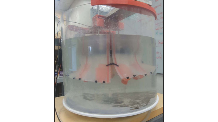
Test setup photo (no slide title present on this page)
A full-frame photograph of the jellyfish robot in its cylindrical test tank. The robot has a pink and translucent bell with segmented panels extending outward, small dark sensor markers spaced along the bottom edge of the bell, and a red mounting fixture with wires visible above the water surface. A whiteboard with handwritten notes is visible in the background.
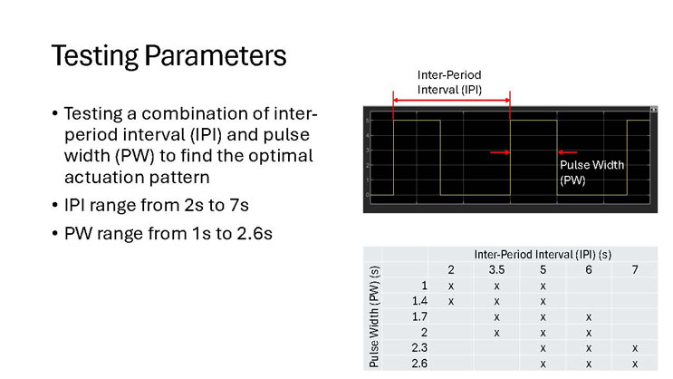
Testing Parameters
- Testing a combination of inter-period interval (IPI) and pulse width (PW) to find the optimal actuation pattern
- IPI range from 2s to 7s
- PW range from 1s to 2.6s
Diagram: a square wave signal with "Inter-Period Interval (IPI)" labeling the time from the start of one pulse to the start of the next, and "Pulse Width (PW)" labeling the duration each pulse stays on.
| Pulse Width (PW) (s) | IPI = 2 | IPI = 3.5 | IPI = 5 | IPI = 6 | IPI = 7 |
|---|---|---|---|---|---|
| 1 | x | x | x | ||
| 1.4 | x | x | x | ||
| 1.7 | x | x | x | ||
| 2 | x | x | x | ||
| 2.3 | x | x | x | ||
| 2.6 | x | x | x |
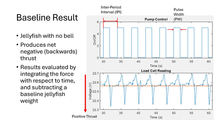
Baseline Result
- Jellyfish with no bell
- Produces net negative (backwards) thrust
- Results evaluated by integrating the force with respect to time, and subtracting a baseline jellyfish weight
Top chart, titled "Pump Control": an on/off square wave plotted from 30 to 60 seconds, with "Inter-Period Interval (IPI)" marking the spacing between pulse starts and "Pulse Width (PW)" marking each pulse's duration.
Bottom chart, titled "Load Cell Reading": voltage plotted from about 22.3 to 22.7 volts over the same time range, oscillating with each pump pulse. A downward red arrow labeled "Positive Thrust" points down the left side of the chart, indicating that downward voltage deflections correspond to positive thrust and the trace shows the reading dipping below baseline more than it rises above it, consistent with net negative thrust.
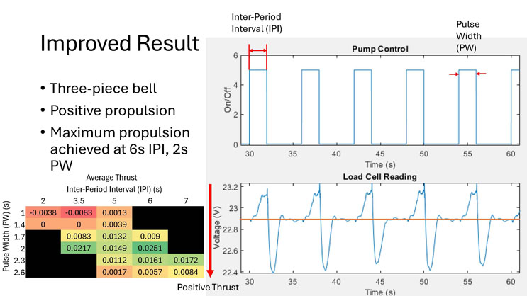
Improved Result
- Three-piece bell
- Positive propulsion
- Maximum propulsion achieved at 6s IPI, 2s PW
| Pulse Width (PW) (s) | IPI = 2 | IPI = 3.5 | IPI = 5 | IPI = 6 | IPI = 7 |
|---|---|---|---|---|---|
| 1 | -0.0038 | -0.0083 | 0.0013 | ||
| 1.4 | 0 | 0 | 0.0039 | ||
| 1.7 | 0.0083 | 0.0132 | 0.009 | ||
| 2 | 0.0217 | 0.0149 | 0.0251 | ||
| 2.3 | 0.0112 | 0.0161 | 0.0172 | ||
| 2.6 | 0.0017 | 0.0057 | 0.0084 |
Top chart, titled "Pump Control": an on/off square wave plotted from 30 to 60 seconds, with "Inter-Period Interval (IPI)" marking the spacing between pulse starts and "Pulse Width (PW)" marking each pulse's duration.
Bottom chart, titled "Load Cell Reading": voltage plotted from about 22.4 to 23.2 volts over the same time range, oscillating with each pump pulse. A downward red arrow labeled "Positive Thrust" points down the left side of the chart. Unlike the baseline result, the trace shows the reading rising further above baseline than it dips below, consistent with net positive thrust.
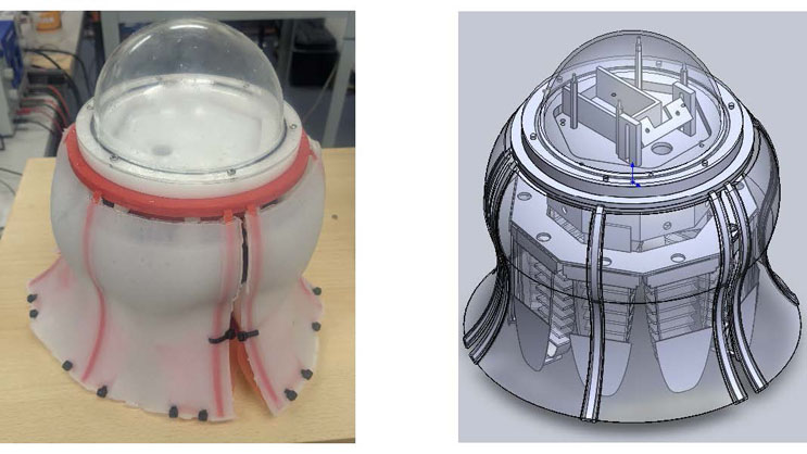
Final jellyfish design (no slide title present on this page)
Left image: a photograph of the assembled jellyfish robot, showing a clear domed top with a red mounting ring, a soft white bell with red reinforcement lines and a three-piece split, and dark sensor markers along the bell's lower edge.
Right image: a CAD rendering of the same jellyfish assembly, showing the clear dome, internal support frame, and translucent bell panels with attached ribbed actuators.
End of Presentation
Click the right arrow to return to the beginning of the slide show.
For a downloadable version of this presentation, email: I-SENSE@FAU.